AEM Series 2 Plug Play EMS 306052 User Manual
Here you can view all the pages of manual AEM Series 2 Plug Play EMS 306052 User Manual. The AEM manuals for Series 2 Plug & Play EMS are available online for free. You can easily download all the documents as PDF.
Page 1
ADVANCED ENGINE MANAGEMENT INC. 2205 126 th Street Unit A Hawthorne, CA. 90250 Phone: (310) 484-2322 Fax: (310) 484-0152 Http://www.aempower.com Instruction Part Number: 10-6050 2009 Advanced Engine Management, Inc. Page 1 of 11 Installation Instructions for: EMS P/N 30-6052 2000-2005 Honda S2000 WARNING: ! This installation is not for the tuning novice nor the PC illiterate! Use this system with EXTREME caution! The AEM EMS System allows for total flexibility in...
Page 2
Page 2 of 11
Thank you for purchasing an AEM Engine Management System.

The AEM Engine Management System (EMS) is the resul t of extensive development on a
wide variety of cars. Each system is engineered for  the particular application. The AEM
EMS differs from all others in several ways. The EM S is a stand alone system, which
completely replaces the factory ECU and features un ique Plug and Play Technology,
which means that each system is configured especial ly for your make and model of car...
Page 3
Page 3 of 11
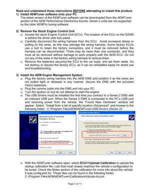
Read and understand these instructions BEFORE attempting to install this product.
1)  Install AEMTuner software onto your PC   The latest version of the AEMTuner software can be  downloaded from the AEMTuner
section of the AEM Performance Electronics forums.  Series 2 units are not supported
by the older AEMPro tuning software.

2)  Remove the Stock Engine Control Unit
a) Access the stock Engine Control Unit (ECU). The loc ation of the ECU on the S2000
is behind the driver side...
Page 4
Page 4 of 11
f)
Set the throttle range: Select Wizards>>Set Throttl
e Range and follow the on-
screen instructions. When finished, check that the  ‘Throttle’ channel never indicates
less than 0.2% or greater than 99.8%, this is consi dered a sensor error and may
cause some functions including idle feedback and ac celeration fuel to operate
incorrectly.
4)  Ready to begin tuning the vehicle.
a) Before  starting  the  engine,  verify  that  the  fuel  pu mp  runs  for  a  couple  of  seconds...
Page 5
Page 5 of 11
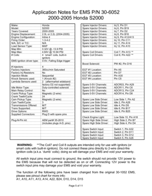
Application Notes for EMS P/N 30-6052 2000-2005 Honda S2000

Make:  Honda    Spare Injector Drivers:  Inj 5, Pin D1
Model:  S2000    Spare Injector Drivers:  Inj 6, Pin B1 9
Years Covered:  2000-2005    Spare Injector Drivers:  Inj 7, Pin D2
Engine Displacement:  2.0L or 2.2L (2004-2005)    Spare Injector Drivers:  Inj 8, Pin B16
Engine Configuration:  Inline 4    Spare Injector Driv ers:  Inj 9, Pin A12/A13
Firing Order:  1-3-4-2    Spare Injector Drivers:  Inj  10, Pin C11
N/A,...
Page 6
Page 6 of 11

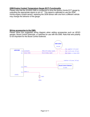
OEM Engine Coolant Temperature Gauge (ECT) Function
ality
Please note that the 30-6052 EMS is configured to d rive the factory Honda ECT gauge by
outputting the appropriate signal on pin A1.  This  signal is calibrated to use the OEM
Honda engine coolant sensor; replacing the OEM sens or with one from a different vehicle
may change the behavior of the gauge.

Wiring accessories to the EMS:
Please  follow  this  suggested  wiring  diagram  when  ad ding  accessories  such...
Page 7
Page 7 of 11
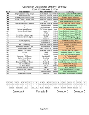
Connection Diagram for EMS P/N 30-6052 2000-2005 Honda S2000
Pin # 2000-2005 S2000 AEM EMS 30-6052 I/O Availability
A1 Engine Coolant Temp Gauge  Coolant dash signal Output Dedicated, works with AP1 and AP2
A2  Air Control Valve  Low Side Driver 1  Output Avail, Switched Ground, 1.5A Max
A3 EVAP Bypass Solenoid Valve  Low Side Driver 3  Output PnP For Bypass Solenoid
A4  EVAP Control Canister Vent  Low Side Driver 5  Output PnP For Control Canister Vent
A5  ---  EGT 1  Input Avail,...
Page 8
Page 8 of 11

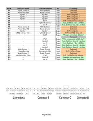
Pin # 2000-2005 S2000 AEM EMS 30-6052 I/O Availability
B1
Power Source 1  +12V Switched  Both Dedicated
B2 Power Ground 1  Power Ground  Both Dedicated
B3  Injector 2  Injector 2  Output PnP For Injector 2
B4 Injector 3  Injector 3  Output PnP For Injector 3
B5 Injector 4  Injector 4  Output PnP For Injector 4
B6  ---  PW 1i  Output PnP For Idle Control Solenoid
B7 ---  High Side Driver 2  Output Avail, Switched +12v, 1.5A Max
B8 ---  Idle #5  Output Avail, Switched Ground, 1.5A...
Page 9
Page 9 of 11

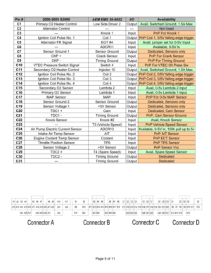
Pin # 2000-2005 S2000 AEM EMS 30-6052 I/O Availability
C1
Primary O2 Heater Control  Low Side Driver 2  Output Avail, Switched Ground, 1.5A Max
C2  Alternator Control  ---  --- Not Used
C3  ---  Knock 1  Input PnP For Knock 1
C4 Ignition Coil Pulse No. 1  Coil 1  Output PnP Coil 1, 0/5V falling edge trigger
C5  Alternator FR Signal  EGT #4  Input Avail, jumper set for 0-5V Input
C6  ---  ADCR11  Input Available, 0-5V in
C7 Sensor Ground 1  Sensor Ground  Output Dedicated, Sensors...
Page 10
Page 10 of 11

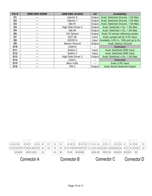
Pin # 2000-2005 S2000 AEM EMS 30-6052 I/O Availability
D1
---  Injector 5  Output Avail, Switched Ground, 1.5A Max
D2 ---  Injector 7  Output Avail, Switched Ground, 1.5A Max
D3 ---  Idle #1  Output Avail, Switched Ground, 1.5A Max
D4 ---  High Side Driver 4  Output Avail, Switched +12v, 1.5A Max
D5 ---  Idle #4  Output Avail, Switched +12v, 1.5A Max
D6 ---  +5V Sensor  Output Avail, 5V sensor reference power
D7 ---  EGT #2  Input Avail, jumper set for 0-5V Input
D8 ---  ADCR14...
