AEM Serial Data Stream Gauge 304300 User Manual
Here you can view all the pages of manual AEM Serial Data Stream Gauge 304300 User Manual. The AEM manuals for Digital Performance Gauges are available online for free. You can easily download all the documents as PDF.
Page 1
ADVANCED ENGINE MANAGEMENT INC.
2205 126th Street Unit A, Hawthorne, CA. 90250
Phone: (310) 484-2322 Fax: (310) 484-0152
http://www.aempower.com
Instruction Part Number: 10-4300 Rev 112205
© 2005 Advanced Engine Management, Inc.


Page 1


Installation Instructions for
30-4300
AEM Serial Gauge


WARNING:

,!
This installation is not for the electrically or mechanically
challenged! Use this gauge with EXTREME
 caution! If you are
uncomfortable with anything about this, please...
Page 2
Page 2
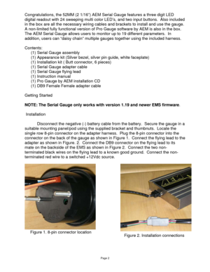
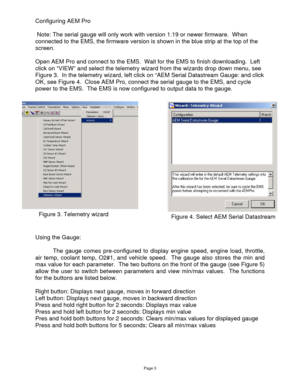
Congratulations, the 52MM (2 1/16”) AEM Serial Gauge features a three digit LED
digital readout with 24 sweeping multi color LED’s, and two input buttons.  Also included
in the box are all the necessary wiring cables and brackets to install and use the gauge.
A non-limited fully functional version of Pro Gauge software by AEM is also in the box.
The AEM Serial Gauge allows users to monitor up to 19 different parameters.  In
addition, users can “daisy chain” multiple gauges together using...
Page 3
Page 3
Configuring AEM Pro

 Note: The serial gauge will only work with version 1.19 or newer firmware.  When
connected to the EMS, the firmware version is shown in the blue strip at the top of the
screen.

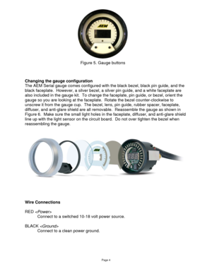
Open AEM Pro and connect to the EMS.  Wait for the EMS to finish downloading.  Left
click on “VIEW” and select the telemetry wizard from the wizards drop down menu, see
Figure 3.  In the telemetry wizard, left click on “AEM Serial Datastream Gauge: and click
OK, see Figure 4.  Close AEM...
Page 4
Page 4


Changing the gauge configuration
The AEM Serial gauge comes configured with the black bezel, black pin guide, and the
black faceplate.  However, a silver bezel, a silver pin guide, and a white faceplate are
also included in the gauge kit.  To change the faceplate, pin guide, or bezel, orient the
gauge so you are looking at the faceplate.  Rotate the bezel counter-clockwise to
unscrew it from the gauge cup.  The bezel, lens, pin guide, rubber spacer, faceplate,...
Page 5
Page 5

*BROWN
Connect to negative side of warning device, 1 amp max.

*ORANGE
Connect to negative side of warning device, 1 amp max.

GREEN ,

*optional


Visit the AEM electronics forum for instructions on how to use the Pro Gauge
software.

AEM Electronics Warranty

Advanced Engine Management Inc. warrants to the consumer that all AEM Electronics
products will be free from defects in material and workmanship for a period of twelve
months from date of the original purchase....
Page 6
 Pro Gauge
by AEM

Revision:
Revision Date:
Page:


B
02/20/2007
 1
AEM ProGauge Software

Note:  The AEM Serial Gauge is factory pre loaded with “BASE CAL.mdb”, which
displays the following parameters:
• Engine Load
• Throttle Position
• Air Temp
• O2 #1
• Vehicle Speed

Connecting to the Gauge

1.  Install AEM ProGauge software from provided CD, or check Electronics Forums
on WWW.AEMPOWER.COM
 for latest software.
2.  Start with the Serial Gauge powered off.
3.  Connect...
Page 7
 Pro Gauge
by AEM

Revision:
Revision Date:
Page:


B
02/20/2007
 2
Changing Displayed Gauges

To change your displayed gauges, select the “Single gauge data” window  it is
located at the top of the screen, it is usually the window on top. In the bottom left hand of
the window there is a “Gauge Order” selection box.  The “Gauges” in the “In-use” column
are the “Gauges” that are loaded and are active on the Serial Gauge.  The gauges in the
“Available” column are NOT loaded, therefore...
Page 8
 Pro Gauge
by AEM

Revision:
Revision Date:
Page:


B
02/20/2007
 3

Low Alarm - Alarm is triggered when this value is reached

High Alarm - Alarm is triggered when this value is reached

Clear Min/Max History on Power-up - When Checked, the min and max values for the
selected gauge will be cleared when the power is cycled.

Low History Delay - This is the amount of time that a parameter must exceed the
existing low value before being recorded as the new low.  For example, if...
Page 9
 Pro Gauge
by AEM

Revision:
Revision Date:
Page:


B
02/20/2007
 4
Look-Up Table
  To Open the Lookup Table for a gauge, open the single gauge data window, then
click on the gray bar all the way to the left as shown in Figure 4.  The gauge display
name and units can be changed by changing the text in the Gauge Name and Units
text boxes.

Changing the displayed name and units
  To change the displayed name, open the look up table in the top right hand corner
there is a box...
Page 10
 Pro Gauge
by AEM

Revision:
Revision Date:
Page:


B
02/20/2007
 5
Figure 4. Selecting a look-up table


Figure 5. Look-up Table

Auto Fill
  The Auto Fill function can be used to make user defined ranges easily
programmable. In the look up table click on the Auto Fill icon on the bottom of the table,
this will open another window; Enter your start cell number (Item number), stop cell (Item
Number) and the start and end values  Click Fill Table...


