AEM Series 2 Plug Play EMS 306053 User Manual
Here you can view all the pages of manual AEM Series 2 Plug Play EMS 306053 User Manual. The AEM manuals for Series 2 Plug & Play EMS are available online for free. You can easily download all the documents as PDF.
Page 1
Page 1 of 21


Installation Instructions for:
EMS P/N 30-6053

Fits vehicles:
2006-2008 Honda S2000 AP2 F22C1


WARNING:

,!
This installation is not for the tuning novice nor the PC illiterate!
Use this system with EXTREME
 caution! The AEM EMS System
allows for total flexibility in engine tuning. Misuse of this
product can destroy your engine! If you are not well versed in
engine dynamics and the tuning of management systems or are
not PC literate, please do not attempt the...
Page 2
Page 2 of 21
Thank you for purchasing an AEM Engine Management System.

The AEM Engine Management System (EMS) is the result of extensive development on a
wide variety of cars. Each system is engineered for each particular application. The AEM
EMS differs from all others in several ways. The EMS is a stand alone system which
replaces the fuel and ignition functions of the factory ECU and features unique Plug and Play
Technology, which means that each system is configured especially for your make...
Page 3
Page 3 of 21
Read and understand these instructions BEFORE attempting to install this product.
• Sufficient battery voltage during cranking (starting)
Having enough battery voltage when you crank over your vehicle is critical to the
operation of your vehicle and your AEM EMS. For the EMS to function properly, the
battery voltage must remain at or above 8 Volts when the vehicle is first starting. This
is the time when your electrical system will be worked its hardest and be at its lowest
voltage....
Page 4
Page 4 of 21
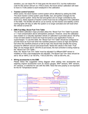
sensitive, you can depin Pin A1 that goes into the stock ECU, but the malfunction
code for this sensor will turn on. If this is done, the knock sensor calibration will need
to have 0.3 Volts added to each breakpoint in the calibration.

• Traction control function
When active, the stock traction control system will be affected by adding the EMS.
The stock traction control system uses throttle, fuel, and ignition changes for the
traction control system. Since the fuel and ignition are...
Page 5
Page 5 of 21
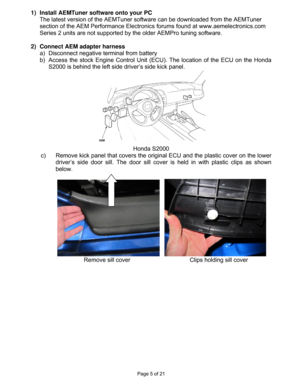
1)  Install AEMTuner software onto your PC
The latest version of the AEMTuner software can be downloaded from the AEMTuner
section of the AEM Performance Electronics forums found at www.aemelectronics.com
Series 2 units are not supported by the older AEMPro tuning software.

2)  Connect AEM adapter harness
a)  Disconnect negative terminal from battery
b)  Access the stock Engine Control Unit (ECU). The location of the ECU on the Honda
S2000 is behind the left side driver’s side...
Page 6
Page 6 of 21
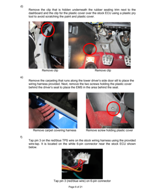
d)
Remove the clip that is hidden underneath the rubber sealing trim next to the
dashboard and the clip for the plastic cover over the stock ECU using a plastic pry
tool to avoid scratching the paint and plastic cover.


Remove clip     Remove clip

e)
Remove the carpeting that runs along the lower driver’s side door sill to place the
wiring harness provided. Next, remove the two screws holding the plastic cover
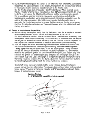
behind the driver’s seat to place the EMS in the area behind the...
Page 7
Page 7 of 21
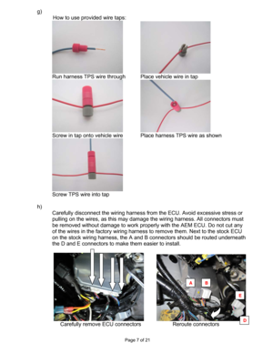
g)
How to use provided wire taps:

Run harness TPS wire through   Place vehicle wire in tap

Screw in tap onto vehicle wire  Place harness TPS wire as shown

Screw TPS wire into tap

h)
Carefully disconnect the wiring harness from the ECU. Avoid excessive stress or
pulling on the wires, as this may damage the wiring harness. All connectors must
be removed without damage to work properly with the AEM ECU. Do not cut any
of the wires in the factory wiring harness to remove...
Page 8
Page 8 of 21
i)
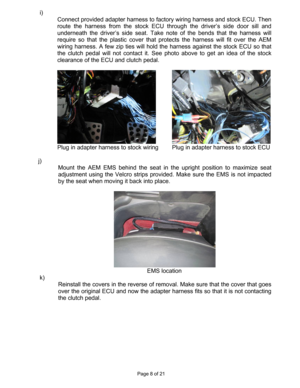
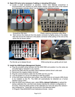
Connect provided adapter harness to factory wiring harness and stock ECU. Then
route the harness from the stock ECU through the driver’s side door sill and
underneath the driver’s side seat. Take note of the bends that the harness will
require so that the plastic cover that protects the harness will fit over the AEM
wiring harness. A few zip ties will hold the harness against the stock ECU so that
the clutch pedal will not contact it. See photo above to get an idea of the stock...
Page 9
Page 9 of 21
2)  Repin ECU pins (only necessary if adding or relocating ECU pins)
a) Locate a small screwdriver (a precision 1.5mm wide flathead screwdriver is
recommended) and carefully pry white plastic retainer using both slots in the retainer
so it disengages vertically about 1mm as shown in the following pictures:

        Screwdriver lifts here       Plastic retaining mechanism after lifting
b)    Next remove the metal pin from the plastic connector by lightly prying on the plastic
tabs...
Page 10
Page 10 of 21
h)  NOTE: the throttle range on this vehicle is set differently from other EMS applications!
Disconnect the DBW connector on the throttle, then perform the procedure as follows
by holding the throttle open and closed manually at the throttle plate.
Set the throttle range: Select Wizards>>Set Throttle Range. When finished, check
that the ‘Throttle’ channel never indicates less than 3.2% or greater than 99.8% (must
be 2.2% or more since the DBW throttle will close slightly when the...


