AEM Series 2 Plug Play EMS 306601 User Manual
Here you can view all the pages of manual AEM Series 2 Plug Play EMS 306601 User Manual. The AEM manuals for Series 2 Plug & Play EMS are available online for free. You can easily download all the documents as PDF.
Page 1
ADVANCED ENGINE MANAGEMENT INC.
2205 126
th Street Unit A    Hawthorne, CA. 90250
Phone: (310) 484-2322 Fax: (310) 484-0152
http://www.aempower.com
Instruction Part Number: 10-6601
© 2010 Advanced Engine Management, Inc.

Page 1 of 13
Installation Instructions for:
EMS P/N 30-6601
1991-1993 Silvia S13 SR20DET
1991-1995 Nissan 180SX SR20DET

WARNING:
,!
This installation is not for the t uning novice nor the PC illiterate!
Use this system with
EXTREME caution! The AEM EMS System...
Page 2
Thank you for purchasing an AEM Engine Management System.

The AEM Engine Management System (EMS) is  the result of extensive development on a
wide variety of cars. Each system is enginee red for the particular application. The AEM
EMS differs from all others in several  ways. The EMS is a stand alone system, which
completely replaces the factory ECU and  features unique Plug and Play Technology,
which means that each system is configured  especially for your make and model of car
without any...
Page 3
Read and understand these instructions BEFORE attempting to install this product.
1)  Install AEMTuner software onto your PC
The latest version of the AEMTuner so ftware can be downloaded from the AEMTuner
section of the AEM Perform ance Electronics forums. Seri es 2 units are not supported
by the older AEMPro tuning software.

2)  Change Cam/Crank Angle Sensor: AEM trigger disc MUST be used
On Nissans, discrepancies have been observed  in the OEM cam/crank angle signals
between model...
Page 4
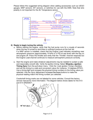
Please follow this suggested wiring diagram when adding accessories such as UEGO
gauges, MAP sensors, IAT sensors, or switches for use with the EMS. Note that wire
polarity is not important for t he Air Temperature sensor.
+5V Sensor Power
Switched Input
41 Sensor Ground
IAT Sensor
29 26
AEM EMS
P/N: 30-6600
Sensor Ground
MAP Signal
35
29 37 Sensor Ground O2 Sensor 1
19
29
Ground Switch 6
Air Temperature Sensor
P/N: 30-2010
Black (Sensor Ground)Green (MAP Signal)
Red (+5V Sensor Power) Black...
Page 5
c) Note: This calibration needs to be properly tuned before driving the vehicle. It is
intended for racing vehicles and may not oper ate smoothly at idle or part-throttle.
NEVER TUNE THE VEHICLE WHILE DRIVING

7) Troubleshooting an engine that will not start
a) Double-check all the basics first… engi nes need air, fuel, compression, and a
correctly-timed spark event. If any of these  are lacking, we suggest checking simple
things first. Depending on the symptoms, it may be best to inspect fuses,...
Page 6
Application Notes for EMS P/N 30-6601
1991-1993 Silvia S13 SR20DET,  1991-1995 180SX SR20DET

Make: Nissan  Spare Injector Drivers: Inj 5, Pin 23
Model: Silvia and 180SX  Spare Injector Drivers: Inj 6, Pin 105
Years Covered: 1991-1995  Spare Injector Drivers: Inj 7, Pin 14
Engine Displacement: 2.0L  Spare Injector Drivers: Inj 8, Pin 114
Engine Configuration: Inline 4
Firing Order: 1-3-4-2
N/A, S/C or T/C: Turbocharged
Load Sensor Type: 0-5V MAF  Boost Solenoid: PW 2, Pin 111
   EGT...
Page 7
Engine Wiring Harnesses, ‘swapped’ engine installations
Many Nissan wiring harnesses have been found  to contain significant differences between
model years and/or trim levels. Likely diffe rences include: Crank signal, Cam signal,
Ignition switch wiring (the Ignition switch input  controls the Main Relay output), injector and
coil destinations. Official document ation for some vehicles was not offered in English, so it
would be very wise to double-c heck the pinout destinations for these circuits....
Page 8
Wiring accessories to the EMS:
Please follow this suggested wiring diagram when adding accessories such as UEGO
gauges, MAP sensors, IAT sensors, or switc hes for use with the EMS. Note that wire
polarity is not important for t he Air Temperature sensor.

Page 8 of 13
Page 9
Connection Diagram for EMS P/N 30-6601
PnP These pins are used in the AEM-supplied startup calibration. They can be reconfigured by the end user.
Available Not used by the startup calibration. Modifications to the OEM wiring may be required before use.
Dedicated The function of these pins is fixed and must not be changed.

Pin  1991-1995 Nissan 180SX SR20DET,  1991-1993 Nissan Silvia S13 SR20DET AEM EMS 30-6601 I/O Notes
1 Ignition 1 Coil 1 Output PnP for Coil 1,  0-5V Falling Edge trigger
2...
Page 10
Connection Diagram for EMS P/N 30-6601
Pin  1991-1995 Nissan 180SX SR20DET,  1991-1993 Nissan Silvia S13 SR20DET AEM EMS 30-6601 I/O Notes
15 Data Link Connector EGT 2 Input Available, jumper set for 0-5V Input
16 Mass Air Flow Sensor MAF Input PnP for MAF Sensor
17 Mass Air Flow Ground Power Ground Input Dedicated
18 ECT Sensor Coolant Input PnP for Coolant Temp Sensor
19 Oxygen Sensor O2 #1 Input Dedicated, 0-5V input signal
20 Throttle Position Sensor TPS Input PnP for Throttle Position Sensor...


