AEM Series 2 Plug Play EMS 306610 User Manual
Here you can view all the pages of manual AEM Series 2 Plug Play EMS 306610 User Manual. The AEM manuals for Series 2 Plug & Play EMS are available online for free. You can easily download all the documents as PDF.
Page 1
© 2010 Advanced Engine Management, Inc.
ADVANCED ENGINE MANAGEMENT INC.
2205 126
th Street Unit A    Hawthorne, CA. 90250
Phone: (310) 484-2322 Fax: (310) 484-0152
http://www.aempower.com
Instruction Part Number: 10-6610

Page 1 of 14
Installation Instructions for:
EMS P/N 30-6610
95 Nissan 240SX S14 KA24DE (OBDI)
95-97 Nissan Sentra and 200SX B14 SR20DE & GA16DE (Except 97 1.6L)
95-96 Nissan Altima U13 KA24DE (Except 96 CA models)
94-96 Infiniti G20 P10 SR20DE

WARNING:

,!
This...
Page 2
Page 2 of 14
Thank you for purchasing an AEM Engine Management System.

The AEM Engine Management System (EMS) is the result of extensive development on a
wide variety of cars. Each system is engineered for the particular application. The AEM
EMS differs from all others in several ways. The EMS is a stand alone system, which
completely replaces the factory ECU and features unique Plug and Play Technology,
which means that each system is configured especially for your make and model of car...
Page 3
Page 3 of 14
Read and understand these instructions BEFORE attempting to install this product.
Engine Wiring Harnesses, ‘swapped’ engine installations

Many Nissan wiring harnesses have been found to contain significant differences between
model years and/or trim levels. Likely differences include: Crank signal, Cam signal,
Ignition switch wiring (the Ignition switch input controls the Main Relay output), injector and
coil destinations. Official documentation for these vehicles was not offered in...
Page 4
Page 4 of 14
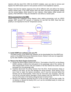
injectors with the stock ECU. With the 30-6610 installed, users can elect to remove and
bypass the OEM resistor pack for more precise control of low-impedance injectors.

Please note that the injector response time will be different with and without the factory
injector resistor pack. If the OEM resistor pack has been removed and bypassed, please
use the correct battery offset wizard for your injectors. Most battery offset wizards will
specify  if they are intended for use without a...
Page 5
Page 5 of 14
3)  Install the AEM Engine Management System
a) Plug the factory wiring harness into the AEM EMS and position it so the wires are
not pulled tight or stressed in any manner. Secure the EMS with the provided
Velcro fasteners.
b) Plug the comms cable into the EMS and into your PC.
c) Turn the ignition on, but do not attempt to start the engine.
d) At the time these instructions were written, new EMS units do not require USB
drivers to be installed on the PC.
e) With the AEMTuner...
Page 6
Page 6 of 14
Crankshaft timing marks are not labeled for some vehicles. Consult the factory
service manual for more information. The diagram below shows labels for the
240SX:


c) Note: This calibration needs to be properly tuned before driving the vehicle. It is
intended for racing vehicles and may not operate smoothly at idle or part-throttle.
NEVER TUNE THE VEHICLE WHILE DRIVING


5) Troubleshooting an engine that will not start
a) Double-check all the basics first… engines need air,...
Page 7
Page 7 of 14  c)
If the Engine Load changes when the throttle is pressed this usually indicates that
there is a problem with the MAP sensor wiring or software calibration (when the
EMS detects that the MAP Volts are above or below the min/max limits it will run in
a failsafe mode using the TPS-to-Load table to generate an artificial Engine Load
signal using the Throttle input). This may allow the engine to sputter or start but not
continue running properly....
Page 8
Page 8 of 14
Application Notes for EMS P/N 30-6610
KA24DE, GA16DE, SR20DE

Make: Nissan/Infiniti   Spare Injector Drivers:  Inj 5, Pin 29
Model:  240SX, Sentra, 200SX, Altima, G20    Spare Injector Drivers:  Inj 6, Pin 30
Years Covered:  1994-1997    Spare Injector Drivers:  Inj 7, Pin 31
Engine Displacement:  1.6L, 2.0L, 2.4L    Spare Injector Drivers:  Inj 8, Pin 32
Engine Configuration:  Inline 4    Spare Injector Drivers:  Inj 9, Pin 116
Firing Order:  1-3-4-2    Spare Injector Drivers:  Inj...
Page 9
Page 9 of 14

30-1610 (Series 1) vs 30-6610 (Series 2) EMS differences:

The EMS functions assigned to certain pins have been changed and no longer match the
30-1610 EMS. Unless otherwise noted, the following pins and functions will need to be
manually reconfigured after using AEMTuner to convert a V1.19 30-1610, Series 1 EMS
calibration for use with the 30-6610 Series 2 hardware.

Pin  Vehicle harness
destination 30-1610 function 30-6610 function Notes
12  A/C triple press sw  ---  CAN1L...
Page 10
Page 10 of 14
Connection Diagram for EMS P/N 30-6610
PnP Means the Plug and Play system comes with this configured for proper operation of this
device. Is still available for reassignment by the end user.
Available  Means the function is not currently allocated and is available for use
Dedicated  Means the location is fixed and cannot be changed

Pin
1995 Nissan 240SX S14 KA24DE (OBDI) 1995-1997 Nissan Sentra B14 SR20DE/GA16DE (x/c ’97 1.6L) 1995-1997 200SX B14 SR20DE/GA16DE (x/c ’97 1.6L)...


