Home
>
American Water Heater
>
Gas Heater
>
American Water Heater Polaris High Efficiency Commercial Gas Water Heater PCG3 User Manual
American Water Heater Polaris High Efficiency Commercial Gas Water Heater PCG3 User Manual
Here you can view all the pages of manual American Water Heater Polaris High Efficiency Commercial Gas Water Heater PCG3 User Manual. The American Water Heater manuals for Gas Heater are available online for free. You can easily download all the documents as PDF.
Page 21
21
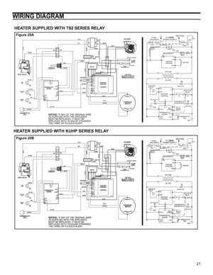
WIRING DIAGRAM
HEATER SUPPLIED WITH T92 SERIES RELAY
HEATER SUPPLIED WITH KUHP SERIES RELAY
NOTICE:  IF ANY OF THE ORIGINAL WIRE
AS SUPPLIED WITH THE APPLIANCE
MUST BE REPLACED, IT MUST BE
REPLACED WITH 18 GAUGE STRANDED
105C WIRE OR ITS EQUIVALENT.THERMOSTAT
      BOARDIGNITION
CONTROL
IGNITION
CONTROL BLOWERHSI
HSIG L1L2 IND
120 VAC
24 VAC
GAS VALVE
     RELAY
RED LED
GREEN LED
YELLOW LED
THERMOSTAT
SENSOR-ECO
C
GV
W
POT N.O.
24 V
 HOT
ONLY COM
THERMOSTAT
        DIAL
     TO 120/60
POWER...
Page 22
22
INSTALLATION CHECKLIST
Water Heater Location
Requirements
… Centrally located with the water piping system. Located
as close to the gas piping and vent pipe system as pos-
sible.
…  Located indoors and in a vertical position. Protected
from freezing temperatures.
…  Proper clearances from combustible surfaces main-
tained and not installed directly on a carpeted floor.
Sufficient room to service the water heater.
…  Provisions made to protect the area from water dam-
age. Properly sized metal...
Page 23
23
OPERATING YOUR WATER HEATER
Read and understand these directions thoroughly before
attempting to operate the water heater (see Operating
Instructions on Page 24).  Check the data plate on the
front of the water heater for the correct gas. Do not use this
water heater with any gas other than the one listed on the
data plate.  If you have any questions or doubts, consult
your gas supplier or gas utility company.
L.P. (Propane) Models
Propane gas is heavier than air and in the occurrence of
a leak...
Page 24
24occurrence of igniter failure due to excessive condensate.
Important:  A mixing valve (provided) must be installed in
the hot water outlet to reduce the risk of scald injury when
setting the thermostat in excess of 120°F (48.9°C).
Many home heating systems
used with this water heater are
designed for temperatures higher
than 130°F (54.4°C). Refer to
the manufacturer’s instruction
manuals supplied with this type
of equipment for recommended
temperature settings.
Important:  Adjusting the...
Page 25
25
OPERATIONAL CONDITIONS
MAINTENANCE
Water Heater Sounds
During the normal operation of the water heater, sounds or
noises may be heard. These noises are common and may
result from the following:
1.  Normal expansion and contraction of metal parts
during periods of heat-up and cool-down.
2.  Sediment buildup in the tank bottom will create varying
amounts of noise and may cause premature tank fail-
ure. Drain and flush the tank as directed under “Drain-
ing and Flushing”.
Safety Shut-Off (Pressure...
Page 26
26
MAINTENANCE OF YOUR WATER HEATER
3 Month Inspection
At least every 3 months, a visual inspection should be
made of the combustion air inlet as well as the exhaust and
water piping.  Check the water heater for the following:
•  Obstructions, damage, or deterioration in the venting
system. Make sure the exhaust and  combustion air
supplies are not obstructed.
•  Leaking or damaged water and gas piping.
•  Presence of flammable or corrosive materials in the
installation area.
•  Presence of...
Page 27
27
TROUBLESHOOTING
  Table 5:
Ignition Control Module (ICM) LED Error Codes: (Flashes visible through viewport in access door)
FLASHES INDICATED PROBLEM CONTROL REACTION
1 Pressure Switch Closed SC*
2 Pressure Switch Open SL
3 Failed Ignition SL3
4 Gas Valve Hardware Fault SL
5 Flame Sense Hardware Fault SC
6 False Flame SL**
8 Ignition Control Hardware Fault SL
9 Ignition Control Software Fault SL
Rapid L1 Polarity Detection SC
SL (Soft Lockout):  Control Automatically resets after 60 minutes.
SL3 (Soft...
Page 29
29
REPAIR PARTS LIST/DIAGRAM
ITEM
NO.PARTS DESCRIPTION
1 1” NPT x 2.5” BRASS NIPPLE
2 THERMOSTAT SENSOR BUSHING
3 O-RING
4 THERMOSTAT SENSOR/ECO
5 INVERTED FLARE NUT
6 PLUG
7 VINYL TUBING
8 PRESSURE SWITCH
9 COMBUSTION BLOWER
10 4 INCH (10.16 cm) DIAMETER BLOWER GASKET
11 BURNER (NATURAL AND L.P. SAME)
12 6 INCH (15.24 cm) DIAMETER BURNER GASKET
13 HOT SURFACE IGNITER
14 IGNITER BRACKET
15 VENTURI MANIFOLD
16 REDUCING COUPLING
17 INLET AIR / FILTER ASSEMBLY
18 GAS VALVE
19 1/2” NPT 90 DEGREE INLET...
Page 30
30
POLARIS MODELS & DIMENSIONS
MODEL
NUMBERGAL.
CAP.INPUT
(MBTU
PER HR.)VENT
DIA. EXTERIORWATER
CONNECTIONST&P
HGTGAS
SUPPLYAIR
INLET/EX-
HAUSTAPPROX
SHIP.
WEIGHT A B C D E F G
PGC* 34-100-2NV OR 2PV 34 100 2 OR 348-1/2 2215-3/4 40-1/2 41 6-3/8 5-1/2 / 6-5/8 150
PGC* 34-130-2NV OR 2PV 34 130 2 OR 348-1/2 22 15-3/440-1/2 41 6-3/8 5-1/2 / 6-5/8 150
PGC* 34-150-2NV OR 2PV 34 150 2 OR 348-1/2 22 15-3/440-1/2 41 6-3/8 5-1/2 / 6-5/8 150
PGC* 50-130-2NV OR 2PV 50 130 2 OR 362-3/8 22 15-3/454-1/2 55...


