Samsung Q1u Service Guide
Here you can view all the pages of manual Samsung Q1u Service Guide. The Samsung manuals for Notebook are available online for free. You can easily download all the documents as PDF.
Page 1
3-1
3. Disassemble and Assemble
1) Q1 Ultra Disassemble and Assemble* Attention to red sentence.
- 이 문서는 삼성전자의 기술 자산으로 승인자만이 사용할 수 있습니다 -
- This Document can not be used without Samsung's authorization -
Part Picture Description
Main
System
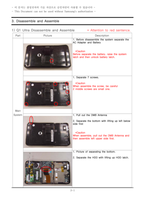
1. Before disassemble the system separate the
AC Adapter and Battery
*Caution
Before separate the battery, raise the system
latch and then unlock battery latch.
1. Separate 7 screws.
*Caution
When assemble the screw, be careful
2 middle screws are small one.
1....
Page 2
3-2
3. Disassemble and Assemble
- This Document can not be used without Samsung's authorization -
Part Picture Description
Main
System
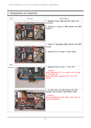
1. Separate Audio cable and Mic cable from
connector
2. Separate 4 screws of DMB Module and DMB
Antenna.
1. Picture of separating DMB antenna and DMB
module.
2. Separate the 5 screws of Main Board.
1. Separate Sub_R, Sub_L, T-Con FPC.
*Caution
When separating FFC, be careful not to brake
of connector pin.
When assemble, assemble the T-Con FPC
exactly.
1. up side down...
Page 3
3-3
3. Disassemble and Assemble
- This Document can not be used without Samsung's authorization -
Part Picture Description
Main
System
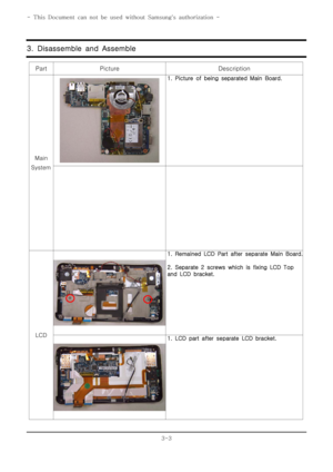
1. Picture of being separated Main Board.
LCD
1. Remained LCD Part after separate Main Board.
2. Separate 2 screws which is fixing LCD Top
and LCD bracket.
1. LCD part after separate LCD bracket.
Page 4
3-4
3. Disassemble and Assemble
- This Document can not be used without Samsung's authorization -
Part Picture Description
LCD
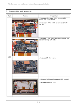
1. Separate silver tape which connect LCD
module and T-Con board.
2. Separate 7 FPCs which is connected to T-
Con B'd.
1. Separate T-Conboardwithliftingupthelcd
latch and sliding right side.
1. Separated T-Con board.
1. Picture of LCD part (separated LCD module)
2. Separate Right/Left FFC.
Page 5
3-5
3. Disassemble and Assemble
- This Document can not be used without Samsung's authorization -
Part Picture Description
LCD
1. Picture after separate FFC.
2. Lifting up LCD module.
1. Separated LCD module.
1. Picture which is separated LCD module.
1. Separate Left Touch Button FFC from
connector.
2. Separate 2 screws which is connecting TOP
and Left board.
Page 6
3-6
3. Disassemble and Assemble
- This Document can not be used without Samsung's authorization -
Part Picture Description
LCD
1. Separated picture.
From upper side, Hall MOUSE, LEFT B'd, Finger
print B'd
1. Separate Right Key pad FCT from Right B'd.
2. Separate 2 screws which is connected with
LCD Top.
1. Separated picture.
From upper side, Right Board and Bluetooth.
1. Picture of Camera B'd is connected with LCD
Top.
2. Separate the camera module with
disassembling 2 screws.
Page 7
3-7
3. Disassemble and Assemble
- This Document can not be used without Samsung's authorization -
Part Picture Description
LCD
1. Separated camera module.
1. Picture which Left Key pad and bracket is
fixedtoTOP.
2. By pushing inside of the 4 latchs which
fixing bracket, separate the Key pad FPC.
1. Picture which Right Key pad and bracket is
fixedtoTOP.
2. By pushing inside of the 4 latchs which
fixing bracket, separate the Key pad FPC.
1. Picture of separated Right/Left Key pad FPC.


