Sony Receiver ICF 7600D ICF 7600DS Operating Instructions
Here you can view all the pages of manual Sony Receiver ICF 7600D ICF 7600DS Operating Instructions. The Sony manuals for Communications receiver are available online for free. You can easily download all the documents as PDF.
Page 1
Dietmar Adolf ([email protected])
DRM Reception With
SONY ICF-7600D/DS (ICF-2002/2003)

v1.02  2004-02-09  first released version
v1.10  2004-02-14  external antenna connector, EMI suppression, AC harmonics suppression
v2.00  2004-02-17  compact version with lowres pics
This report is intended to help others, but no abso lutely no warranty is granted, if any damages resul t from following these steps.

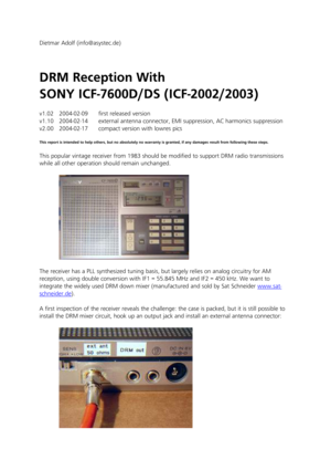
This popular vintage receiver from 1983 should be m odified to support DRM radio...
Page 2
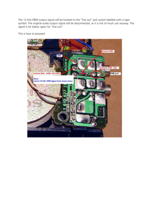
The 12 kHz DRM output signal will be hooked to the “line out” jack socket labelled with a tape
symbol. The original audio output signal will be di sconnected, as it is not of much use anyway. The
signal is far below specs for “line out”.
This is how to proceed:
Page 3
IF Tapping

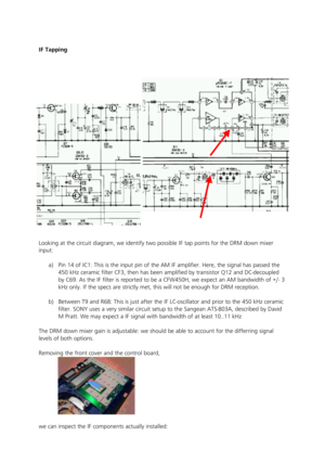
Looking at the circuit diagram, we identify two pos sible IF tap points for the DRM down mixer
input:
a)  Pin 14 of IC1: This is the input pin of the AM I F amplifier. Here, the signal has passed the
450 kHz ceramic filter CF3, then has been amplified  by transistor Q12 and DC-decoupled
by C69. As the IF filter is reported to be a CFW450 H, we expect an AM bandwidth of +/- 3
kHz only. If the specs are strictly met, this will  not be enough for DRM reception.

b)...
Page 4
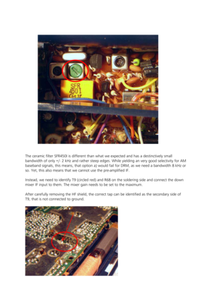
The ceramic filter SFR450I is different than what w e expected and has a destinctively small
bandwidth of only +/- 2 kHz and rather steep edges.  While yielding an very good selectivity for AM
baseband signals, this means, that option a) would  fail for DRM, as we need a bandwidth 8 kHz or
so. Yet, this also means that we cannot use the pre -amplified IF.

Instead, we need to identify T9 (circled red) and R 68 on the soldering side and connect the down
mixer IF input to them. The mixer...
Page 5
As it turns out, the correct pin is about the only  pin of T9, that is accessible without removing the
HF shield:


DC supply  for the DRM mixer

For its AC-Adaptor, SONY used a transformer with a  simple half-bridge and load capacity. Ripples
with 5 % of the nominal voltage (6 V) remain. Regul ator transistors within the receiver further
stabilize the DC supply voltage: Q30 supplies 5.2 V  for the AM circuit. The DRM circuit easily draws
its power from this tap. Also, we can...
Page 6
(range 5.4 .. 8 V) and has an integrated voltage regulator. We found that the mixer SA612A still
operates at around 4 V.
To achieve DRM reception with low batteries, we  need to tap the mixer supply voltage from
the emitter of Q30 . The tap is readily accessible:


The  DRM mixer  board can be placed near the load speaker. To shiel d interferences with the ferrite
antenna, it was wrapped with paper and  aluminum foil.
Page 7
HF Noise Suppression / External Antenna
HF noise picked up by the cable linking the DRM IF out jack and the sound card impaired the
overall reception of regular SW signals while the D RM output was connected.

With the DRM down mixer, the 12 kHz DRM output sign al passes a simple band filter favoring the
range 1..20 kHz and suppressing HF noise. The imped ances of the DRM output (around 2 kOhms)
and the sound card “line in” (around 5 kOhms) are m atched fair enough not to expect further
signal...
Page 8
Results   - The behavior of the AM IF handling is only slightly  degraded. The AM 2
nd mixer is only
offset about a few kHz with the new device installe d. This may be corrected by fine tuning.

-  Adjusting the the LC oscillator of the DRM down mix er is critical and needs some very
careful adjustments.
-  The total power consumption of the receiver is incr eased by 5 mA to a maximum of 55 mA
in AM mode (The DRM mixer is powerless in FM mode u sing 45 mA).

-  Typically the DRM signal was...


