Sony Vx8 Owners Manual
Here you can view all the pages of manual Sony Vx8 Owners Manual. The Sony manuals for Home Audio are available online for free. You can easily download all the documents as PDF.
Page 1
Ð 1 Ð
HCD-VX8/VX8J
E Model
SPECIFICATIONS
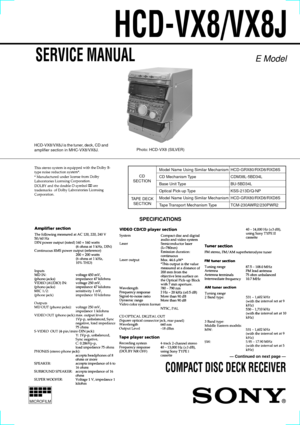
Photo: HCD-VX8 (SILVER)
COMPACT DISC DECK RECEIVER
Ñ Continued on next page Ñ
Model Name Using Similar Mechanism HCD-GRX80/RXD8/RXD8S
CD Mechanism Type CDM38L-5BD34L
Base Unit Type BU-5BD34L
Optical Pick-up Type KSS-213D/Q-NP
Model Name Using Similar Mechanism HCD-GRX80/RXD8/RXD8S
Tape Transport  Mechanism Type TCM-230AWR2/230PWR2
CD
SECTION
TAPE DECK
SECTION
MICROFILM
SERVICE MANUAL
HCD-VX8/VX8J is the tuner, deck, CD and
amplifier section in MHC-VX8/VX8J.
Page 2
Ð 2 Ð
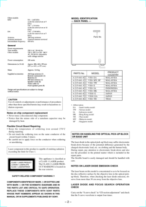
NOTES ON HANDLING THE OPTICAL PICK-UP BLOCK
OR BASE UNIT
The laser diode in the optical pick-up block may suffer electrostatic
break-down because of the potential difference generated by the
charged electrostatic load, etc. on clothing and the human body.
During repair, pay attention to electrostatic break-down and also
use the procedure in the printed matter which is included in the
repair parts.
The flexible board is easily damaged and should be handled with
care.
NOTES ON LASER DIODE EMISSION...
Page 3
Ð 3 Ð
TABLE OF CONTENTS
1. SERVICING NOTE
.......................................................... 4
2. GENERAL.......................................................................... 5
3. DISASSEMBLY
3-1. Loading Panel ....................................................................... 7
3-2. Front Panel and Video Board ................................................ 7
3-3. Cassette Lid and Tape Mechanism ........................................ 8
3-4. CD SW Board and Panel Board...
Page 4
Ð 4 Ð
CD-TEXT
This unit is provided with a simple CD-TEXT display function.
The CD-TEXT contents of 20 tracks are displayed on the fluorescent display tube.
Since the function is simple, some special characters may not be displayed, or may be displayed as other characters.
SECTION 1
SERVICING NOTE
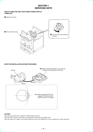
HOW TO OPEN THE DISC TRAY WHEN POWER SWITCH
TURNS OFF
NOTE FOR INSTALLATION (ROTARY ENCODER)
3 Pull-out the disc tray.
1 Remove the Case.
2 Turn the cam to the direction
     of arrow.
BU cam
GrooveSection...
Page 5
Ð 5 Ð
LOCATION OF PARTS AND CONTROLS
11/u (Power) button and indicator
2DEMO (STANDBY) button
3DISC 1 button and indicator
4DISC 2 button and indicator
5DISC 3 button and indicator
6DISC SKIP/EXÐCHANGE button
7¤ (Eject) button
8Disc tray
9EDIT DIRECTION/TUNER MEMORY
button
10PLAY MODE/DOLBY NR button
11REPEAT/STEREO/MONO button
12p button
13^ (CD) button and indicator
14TUNER/BAND button
15CD NON-STOP button and indicator
16KARAOKE PON/MPX button
17SYNC EQ button
18SYNC BASS button
19REC PAUSE/START...
Page 7
Ð 7 Ð
SECTION 3
DISASSEMBLY
Note: Follow the disassembly procedure in the numerical order given.
3-1. LOADING PANEL
3-2. FRONT PANEL AND VIDEO BOARD
3 Loading panel
2 Pull-out the disc tray.
1 Turn the cam to the direction
     of arrow. Claws
3 Screw (BVTT 3x6)
4 Screw (BVTT 3x6)
0 Front panel
!¢ Screw (BVTP 3x8)
!° Video board
6 Screw (BVTP 3x10)
!£ Two screws (BVTP 3x8)
5 Screw
     (BVTP3x10)
1 Screw (BVTT 3x6)
2 Screw (BVTT 3x6)
7 Flat type wire
     (CN501)
8 Flat type wire
     (CN304)
Lead...
Page 8
Ð 8 Ð
3-3. CASSETTE LID AND TAPE MECHANISM
3-4. CD SW BOARD AND PANEL BOARD
1 Release
3 Cassette holder (R)
     assembly
4 Cassette holder (L)
     assembly
Portion
B
Portion B
7 Two screws
     (BVTP2.6x8)
8 Three screws
     (BVTP2.6x8)
9 Tape mechanism
2 Release
     (Refer to order No. 1)
Portion A
Portion A
Note for installation
5 Tension spring
6 Tension spring
4 Knob (Jog)
5 Knob (Vol)
9 Four screws
     (BVTP2.6x8)
3 CD SW board
0 Five screws
     (BVTP2.6x8)
!Á Five screws
     (BVTP2.6x8)!ª...
Page 9
Ð 9 Ð
3-5. DISC TRAY
(Perform after removing the front panel.)Note:When installing the Disc tray, pull around the flat type wire to
         pass through the claw A and claw B, as shown in the figure.
Claw
B
Claw A
1
Turn the cam the
     direction of arrow.
2 Pull-out the disc tray.5 Remove the disc tray.
4 Two claws
3 Flat type wire  (8 core)
Page 10
Ð 10 Ð
SECTION  4
SERVICE MODE
MC Cold Reset
¥ The cold reset clears all data including preset data stored in the RAM to initial conditions. Execute this mode when returning the set to the
customer.
Procedure:
1. Press three buttons  p  ,  ENTER/NEXT  , and  1/u  simultaneously.
2. ÒCOLD RESETÓ is displayed on the fluorescent display tube and reset is executed.
CD Delivery Mode
¥ This mode moves the optical pick-up to the position durable to vibration. Use this mode when returning the set to the customer...


