Acer Aspire 4520 4220 4520G 4220G User Manual
Here you can view all the pages of manual Acer Aspire 4520 4220 4520G 4220G User Manual. The Acer manuals for Notebook are available online for free. You can easily download all the documents as PDF.
Page 11
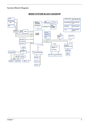
Chapter 15 System Block Diagram CRT AzaliaPCI BusODD (PATA) 3 3 MDC 1.5 TFT LCD Panel 3 XTAL 32.768K 1394 +Cardreader Controller TV-OUT 3 3 3 Speaker 3 PATA Mini Card / WLAN IEEE 1394 Port XTAL 32.768KHZ Audio Amplifier PCI-Express 533/667 MHz CPU Fan 3 USB Port x 4LVDS 3 EC (WPC8769LDG) VGA LPC MONO SYSTEM BLOCK DIAGRAM DDRII SO-DIMM 0 SO-DIMM 1 Phone Jack 3 AMD S1g1 uFCPGA638 Line in USB 2.0 Dual Channel DDR2 3 3 HDD (SATA) 3 Thermal Sensor 3 Azalia...
Page 12

6Chapter 1
Board Layout
Top View
1 LED3 HDD LED 12 CN13 Card Bus Socket
2 LED4 Num Lock LED 13 U12 Winbond Keyboard Controller
3 LED5 Caps Lock LED 14 LED6 Power LED
4 CN3 15 LED7 Battery LED
5 CN4 LCD Connector 16 SW4 Left Click Button Switch
6 U7 17 SW5 Left Scroll Button Switch
7 CN5 Speaker Connector 18 SW3 Up Scroll Button Switch
8 CN10 19 SW6 Right Scroll Button Switch
9 CN7 Keyboard Connector 20 SW8 Down Scroll Button Switch
10 CN8 Touchpad Connector 21 SW7 Right Click Button Switch
11 CN9...
Page 13

Chapter 17
Bottom View
1 CN18 VGA Jack 12 CN26
2 13 CN27 USB Connecto
3 CN19 Battery Connector 14 CN24
4 CN20 S-Video Connector 15 CN28 USB Connecto
5 CN23 Wireless LAN Card Connector 16 CN29 Optical Disk Drive Connector
6 CN22 IEEE 1394 Connector 17 CN30 SATA HDD Connector
7 U20 North Bridge 18 U26 Audio Codec
8 U21 CPU Socket 19 CN32 5-in-1 Card Reader
9 J3 DIMM Socket 20 U29 Infrared Sensor
10 J4 DIMM Socket 21 CN33
11 CN25 Ethernet Controller
11
2 3
423
4
5
7 89 65
7 89
10
10
1414
1212
1313
1515...
Page 14
 that light up to show the status of the computer’s
functions and components.
3 Speaker Left and right speakers deliver stereo audio output.")
8Chapter 1
Your Acer Notebook tour
After knowing your computer features, let us show you around your new Aspire computer.
Front View
#IconItemDescription
1 Built-in camera 0.3 megapixel web camera for video  communication.
2 Status indicators Light-Emitting Diodes (LEDs) that light up  to show the status of the computer’s
functions and components.
3 Speaker Left and right speakers deliver stereo audio  output.
Page 15
The left and right buttons function like the
left and right mouse buttons.
9 Microphone Internal microphone for sound...")
Chapter 19
Closed Front View
4 Wireless communication
button/indicatorEnables/disables the wireless function.
Indicates the status of wireless LAN
communication.
5 Keyboard For entering data into your computer.
6 Touchpad Touch-sensitive  pointing device which
functions like a computer mouse.
7 4-way scroll button To scroll up, down, left, and right.
8 Click buttons (left and  right)The left and right buttons function like the
left and right mouse buttons.
9 Microphone Internal microphone for sound...
Page 16
.
7 Volume control Increases and decreases the volume.
#IconItemDescription
1 External display (VGA) portConnects to a display device (e.g., external
monitor, LCD projector).
2 S-video/TV-out (NTSC/ PAL) port Connects to a television or display device
with S-video input.
3 4-pin IEEE 1394 port Connects to IEEE 1394 devices.
4 Ethernet (RJ-45) Connects to an...")
10Chapter 1
Left View
6 Headphones/speaker/
line-out jack with S/PDIF
supportConnects to audio line-out devices (e.g.,
speakers, headphones).
7 Volume control Increases and decreases the volume.
#IconItemDescription
1 External display (VGA)  portConnects to a display device (e.g., external
monitor, LCD projector).
2 S-video/TV-out (NTSC/ PAL) port Connects to a television or display device
with S-video input.
3 4-pin IEEE 1394 port Connects to IEEE 1394 devices.
4 Ethernet (RJ-45) Connects to an...
Page 17
.
2 Optical disk access indicatorLights up when the optical drive is active.
3 Optical drive eject buttonEjects the optical disk from the drive.
4 Emergency eject hole Ejects the optical drive tray when the
computer is turned off.
5 2 USB 2.0 ports Connect to USB 2.0 devices (e.g., USB mouse, USB camera).
6 DC-in jack Connects to an AC...")
Chapter 111
Right View
Rear view
#IconItemDescription
1 Optical drive Internal optical  drive; accepts CDs or DVDs
(slot-load or tray-load depending on
model).
2 Optical disk access  indicatorLights up when the optical drive is active.
3 Optical drive eject  buttonEjects the optical disk from the drive.
4 Emergency eject hole Ejects the  optical drive tray when the
computer is turned off.
5 2 USB 2.0 ports Connect to USB 2.0 devices (e.g., USB  mouse, USB camera).
6 DC-in jack Connects to an AC...
Page 18

12Chapter 1
Base view
Indicators
The computer has several easy-to-read status indicators.
The front panel indicators are visible even when the computer cover is closed up.
#ItemDescription
1 Battery bay Houses the computer’s battery pack.
2 Battery lock Locks the battery in position.
3 Battery release latch Releases the battery for removal.
4 Ventilation slots and  cooling fan Enable the computer to stay cool, even after prolonged use.
Note: Do not cover or obstruct the opening of the fan.
5 Memory...
Page 19

Chapter 113
NOTE: 1. Charging:  The light shows amber when the battery is charging. 2.  Fully charged: The light shows
green when in AC mode.
Easy-Launch Buttons
To the right of the keyboard there are three ea sy-launch buttons: Web browser, mail, and one user-
programmable button. You can also find an  Empowering Key “  located above the keyboard.
IconFunctionDescription
HDD Indicates when the hard disc or optical drive is active.
Num lock Lights when Num Lock is activated.
Cap lock Lights when Cap...
Page 20
 to move the cursor.
TPress the left (1) and right (4) buttons locat ed beneath the touchpad to perform selection and
execution functions. These...")
14Chapter 1
Press “  “ to run the Acer Empowering Technology. The mail and Web browser buttons are pre-set to email
and Internet programs, but can be reset by users. To  set the Web browser, mail and programmable buttons,
run the Acer Launch Manager.
Touchpad Basics
The following teaches you how to use the touchpad:
TMove your finger across the touchpad (2) to move the cursor.
TPress the left (1) and right (4) buttons locat ed beneath the touchpad to perform selection and
execution functions. These...