Anaheim Stepper 17MDSI Series Users Guide
Here you can view all the pages of manual Anaheim Stepper 17MDSI Series Users Guide. The Anaheim manuals for Stepper are available online for free. You can easily download all the documents as PDF.
Page 1
17MDSI Series
Stepper Motor/Driver/Controller
User’s Guide
910 East Orangefair Lane, Anaheim, CA 92801
e-mail: [email protected](714) 992-6990  fax: (714) 992-0471
website: www.anaheimautomation.com
ANAHEIM AUTOMATION
February 2016L010473
Page 2
General Description
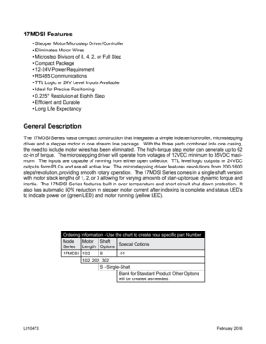
The 17MDSI Series has a compact construction that integrates a simple in\
dexer/controller, microstepping
driver and a stepper motor in one stream line package.  With the three parts combined into one casing,
the need to include motor wires has been eliminated.  The high-torque step motor can generate up to 62
oz-in of torque.  The microstepping driver will operate from voltages of 12VDC minimum to 35VDC maxi-
mum.  The inputs are capable of running from either open collector,  TTL...
Page 3
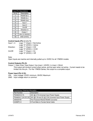
Control Inputs (Pin 4, 5, 6, 7):
Input 1, 2: Logic “1” (Open) = Not Active
    Logic “0” (0VDC) = Active
Direction:  Logic “1” (Open) = CW
    Logic “0” (0VDC) = CCW
On/Off:   Logic “1” (Open) = On
    Logic “0” (0VDC) = Off
Note:
Open Inputs are inactive and internally pulled up to +5VDC for all 17MDS\
I models
Control Outputs (Pin 8):
Output 1: Open Drain Type Output, Vce (max) = 40VDC, Ic (max) = 50mA
  This output will conduct current when active, and be open when not activ\
e.  Current needs to be...
Page 4
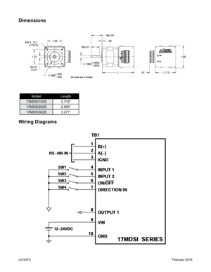
Dimensions
Wiring Diagrams
ModelLength
17MDSI102S 2.719”
17MDSI202S 2.956”
17MDSI302S 3.271”
February 2016L010473
Page 5
Inputs and Outputs
Inputs: All inputs are pulled up to 5VDC. A logic “0” activates inputs that are pulled up.  An un-
connected input will always remain inactive.
Direction: When this input is not active, the motor will be moving in the clockwise or “+” direc-
tion.  When this input is active, the motor will move in the countercloc\
kwise or “-” direction.  This
input is not read when a software index command is given.  To change direction while using the
software, change the direction option there....
Page 6
Baud Rates
The 17MDSI Series only accepts a baud rate of 38400.  A baud rate is a term used frequently in
serial data communicates.  A “baud” is defined as the reciprocal of the shortest pulse duration in
a data word signal, including start, stop, and parity bits.  This is often taken to mean the same as
“bits per second”, a term that expresses only the number of “data” bits per second.  Very often,
The parity bit is included as an information or data bit.
RS485 Protocol
The 17MDSI Series uses a...
Page 7
Motion Profiles and Running the Indexer
The programmable simple indexer has the ability to store two different motion profiles.  The pro-
files include a base speed (starting speed), a maximum speeds (running speed), acceleration/
deceleration, and a number of steps (index) number.  The base speed has a range of 1-5,000Hz,
the maximum speed has a range of 1 Hz-50kHz, the acceleration/decelerati\
on has a range of
100 to 9,999,999 steps/sec
2 and the index has a range of 0-8,388,607 steps.
There are...
Page 8
Functions
Profile Inputs: These inputs are used to select and begin the specified motion profile.  Only 1
input should be activated at a time.
Motion Profiles: The indexer will accept up to two different speed or motion profiles.  Each profile
has it own programmable Accel/Decel, Base speed, Max speed, Index distance value and Com-
plete time.  These values are stored in EEProm for stand-alone use and must be programmed
before the indexer is ran.
Acceleration/Deceleration:  The acceleration and...
Page 9
SMPG-SMSI Software
The SMPG-SMSI software is a handy utility that supports Anaheim Automation’s programmable
pulse generators and simple indexers.  Connecting your PC to the 17MDSI Series stepper motor/
driver/controller, via RS485, the software can easily perform the following tasks:• Exercise and monitor the 17MDSI Series stepper motor/driver/controller
•  Directly communicate with the 17MDSI Series stepper motor/driver/control\
ler
Installation
Software
• The SMPG-SMSI software is supplied on a CD,...
Page 10
“The Unit is Connected” / “The Unit is NOT Connected”
On the right of the Toolbar, the user will find the communication status of the pulse generator.  If
communications is not established, please refer to the troubleshooting s\
ection.
File Menu
Setup Menu
Toolbar
Exit Exit the SMPG10WIN Software
Connect Establish communications with the controller.
Disconnect Discontinue communications and release the comport for use by other devi\
ces.
Communication Settings... COM port Selection (Ports 1, 2, 3, 4,...


