compaq evo n610c and evo n600c User Manual
Here you can view all the pages of manual compaq evo n610c and evo n600c User Manual. The Compaq manuals for Notebook are available online for free. You can easily download all the documents as PDF.
Page 91
5–2Maintenance and Service Guide
Removal and Replacement Procedures
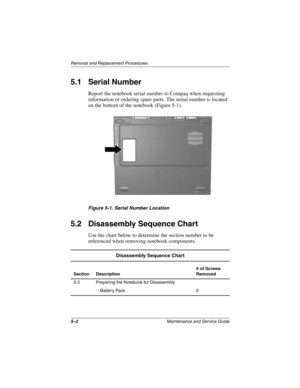
5.1 Serial Number
Report the notebook serial number to Compaq when requesting
information or ordering spare parts. The serial number is located
on the bottom of the notebook (Figure 5-1).
Figure 5-1. Serial Number Location
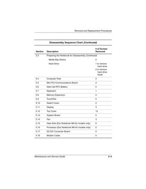
5.2 Disassembly Sequence Chart
Use the chart below to determine the section number to be
referenced when removing notebook components.
Disassembly Sequence Chart
Section Description# of Screws
Removed
5.3 Preparing...
Page 92
Removal and Replacement Procedures
Maintenance and Service Guide5–3
Section Description# of Screws
Removed
5.3 Preparing the Notebook for Disassembly
(Continued)
Media Bay Device 0
Hard Drive 1 to remove
hard drive
2 to remove
hard drive
bezel
5.4 Computer Feet 0
5.5 Mini PCI Communications Board 2
5.6 Disk Cell RTC Battery 0
5.7 Keyboard 1
5.8 Memory Expansion 0
5.9 TouchPad 0
5.10 Switch Cover 2
5.11 Display 3
5.12 Top Cover 12
5.13 System Board 5
5.14 Fan 3
5.15 Heat Sink (Evo Notebook N610c...
Page 93
5–4Maintenance and Service Guide
Removal and Replacement Procedures
5.3 Preparing the Notebook for
Disassembly
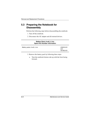
Perform the following steps before disassembling the notebook:
1. Turn off the notebook.
2. Disconnect the AC adapter and all external devices.
3. Remove the battery pack by following these steps:
a. Turn the notebook bottom side up with the front facing
forward.
Battery Pack, 6-cell, Li ion
Spare Part Number Information
Battery packs, 6-cell, Li ion 232633-001
and
301952-001
279362-001.book...
Page 94
Removal and Replacement Procedures
Maintenance and Service Guide5–5
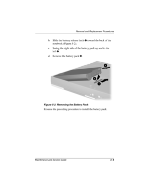
b. Slide the battery release latch 1 toward the back of the
notebook (Figure 5-2).
c. Swing the right side of the battery pack up and to the
left
2.
d. Remove the battery pack
3.
Figure 5-2. Removing the Battery Pack
Reverse the preceding procedure to install the battery pack.
279362-001.book  Page 5  Monday, July 8, 2002  11:49 AM
Page 95
5–6Maintenance and Service Guide
Removal and Replacement Procedures
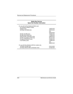
Media Bay Devices
Spare Part Number Information
For use with all Evo Notebook N610c and
Evo Notebook N600c models:
Diskette drive
24X Max CD-ROM drive
8X Max CD-RW drive
8X Max DVD-ROM drive
DVD/CD-RW combination drive
2X Max SuperDisk LS120 drive
IOmega 250-MB ZIP drive
6-cell battery pack135233-001
228746-001
and
228746-001
153992-001
173949-001
238878-001
201274-001
218683-001
100680-001
and
280876-001
For use with Evo Notebook...
Page 96
Removal and Replacement Procedures
Maintenance and Service Guide5–7
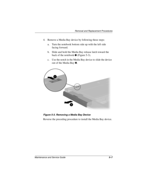
4. Remove a Media Bay device by following these steps:
a. Turn the notebook bottom side up with the left side
facing forward.
b. Slide and hold the Media Bay release latch toward the
back of the notebook
1 (Figure 5-3).
c. Use the notch in the Media Bay device to slide the device
out of the Media Bay
2.
Figure 5-3. Removing a Media Bay Device
Reverse the preceding procedure to install the Media Bay device.
279362-001.book  Page 7...
Page 97
5–8Maintenance and Service Guide
Removal and Replacement Procedures
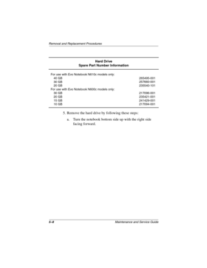
5. Remove the hard drive by following these steps:
a. Turn the notebook bottom side up with the right side
facing forward.
Hard Drive
Spare Part Number Information
For use with Evo Notebook N610c models only:
40 GB
30 GB
20 GB
For use with Evo Notebook N600c models only:
30 GB
20 GB
15 GB
10 GB265495-001
257660-001
235540-101
217096-001
235421-001
241429-001
217094-001
279362-001.book  Page 8  Monday, July 8, 2002  11:49 AM
Page 98
Removal and Replacement Procedures
Maintenance and Service Guide5–9
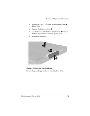
b. Remove the PM2.5 × 2.5 hard drive retention screw 1
(Figure 5-4).
c. Separate the hard drive bezel
2.
d. Use the bezel to slide the hard drive forward
3 to unseat
the hard drive connector from the system board.
e. Remove the hard drive.
Figure 5-4. Removing the Hard Drive
Reverse the preceding procedure to install the hard drive.
279362-001.book  Page 9  Monday, July 8, 2002  11:49 AM
Page 99
5–10Maintenance and Service Guide
Removal and Replacement Procedures
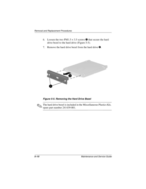
6. Loosen the two PM1.5 × 3.5 screws 1 that secure the hard
drive bezel to the hard drive (Figure 5-5).
7. Remove the hard drive bezel from the hard drive
2.
Figure 5-5. Removing the Hard Drive Bezel
✎The hard drive bezel is included in the Miscellaneous Plastics Kit,
spare part number 241439-001.
279362-001.book  Page 10  Monday, July 8, 2002  11:49 AM
Page 100
Removal and Replacement Procedures
Maintenance and Service Guide5–11
5.4 Computer Feet
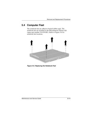
The notebook feet are adhesive-backed rubber pads. The
notebook feet are included in the Miscellaneous Plastics Kit
(spare part number 241439-001). Refer to Figure 5-6 for
notebook feet locations.
Figure 5-6. Replacing the Notebook Feet
279362-001.book  Page 11  Monday, July 8, 2002  11:49 AM
