compaq evo n610c and evo n600c User Manual
Here you can view all the pages of manual compaq evo n610c and evo n600c User Manual. The Compaq manuals for Notebook are available online for free. You can easily download all the documents as PDF.
Page 131
5–42Maintenance and Service Guide
Removal and Replacement Procedures
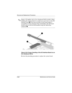
✎Figure 5-29 applies only to Evo Notebook N610c models. When
handling the system board, be careful not to put stress on the I/O
interface board
1. The narrow profile of this board makes it
susceptible to being damaged when mishandled. The I/O board
should only be removed and handled using the Media Bay
connector 2.
Figure 5-29. Proper Handling of the I/O Interface Board on an
Evo Notebook N610c
Reverse the preceding procedure to...
Page 132
Removal and Replacement Procedures
Maintenance and Service Guide5–43
5.14 Fan
1. Prepare the notebook for disassembly (Section 5.3) and
remove the following components:
a. RTC battery (Section 5.6)
b. Keyboard (Section 5.7)
c. Memory expansion compartment cover (Section 5.8)
d. TouchPad (Section 5.9)
e. Switch cover (Section 5.10)
f. Display (Section 5.11)
g. Top cover (Section 5.12)
h. System board (Section 5.13)
2. Turn the system board bottom side up with the rear panel
facing you.
Fan
Spare Part...
Page 133
5–44Maintenance and Service Guide
Removal and Replacement Procedures
3. Disconnect the fan cable from the system board
(Figure 5-30).
Figure 5-30. Disconnecting the Fan Cable
4. Turn the system board top side up with the rear panel
facing you.
279362-001.book  Page 44  Monday, July 8, 2002  11:49 AM
Page 134
Removal and Replacement Procedures
Maintenance and Service Guide5–45
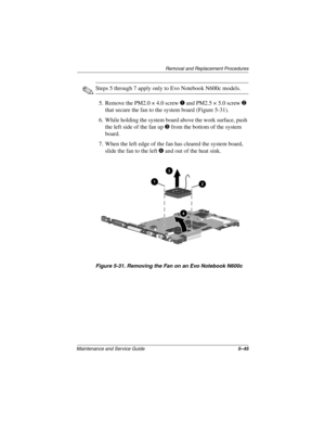
✎Steps 5 through 7 apply only to Evo Notebook N600c models.
5. Remove the PM2.0 × 4.0 screw
1 and PM2.5 × 5.0 screw 2
that secure the fan to the system board (Figure 5-31).
6. While holding the system board above the work surface, push
the left side of the fan up
3 from the bottom of the system
board.
7. When the left edge of the fan has cleared the system board,
slide the fan to the left
4 and out of the heat sink.
Figure 5-31....
Page 135
5–46Maintenance and Service Guide
Removal and Replacement Procedures
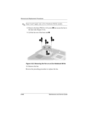
✎Steps 8 and 9 apply only to Evo Notebook N610c models.
8. Remove the three PM2.0 × 4.0 screws
1 that secure the fan to
the heat sink (Figure 5-32).
9. Lift the fan out of the heat sink
2.
Figure 5-32. Removing the Fan on an Evo Notebook N610c
10. Remove the fan.
Reverse the preceding procedure to replace the fan.
279362-001.book  Page 46  Monday, July 8, 2002  11:49 AM
Page 136
Removal and Replacement Procedures
Maintenance and Service Guide5–47
5.15 Heat Sink
✎This section applies only to Evo Notebook N610c models.
1. Prepare the notebook for disassembly (Section 5.3) and
remove the following components:
a. RTC battery (Section 5.6)
b. Keyboard (Section 5.7)
c. Memory expansion compartment cover (Section 5.8)
d. TouchPad (Section 5.9)
e. Switch cover (Section 5.10)
f. Display (Section 5.11)
g. Top cover (Section 5.12)
h. System board (Section 5.13)
Heat Sink
Spare Part Number...
Page 137
5–48Maintenance and Service Guide
Removal and Replacement Procedures
2. Turn the system board bottom side up with the rear panel
facing you.
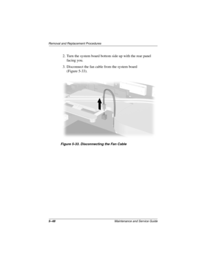
3. Disconnect the fan cable from the system board
(Figure 5-33).
Figure 5-33. Disconnecting the Fan Cable
279362-001.book  Page 48  Monday, July 8, 2002  11:49 AM
Page 138
Removal and Replacement Procedures
Maintenance and Service Guide5–49
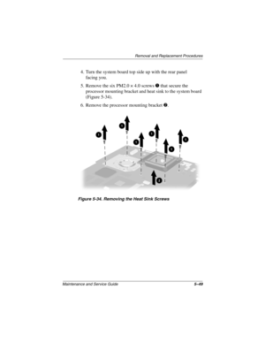
4. Turn the system board top side up with the rear panel
facing you.
5. Remove the six PM2.0 × 4.0 screws
1 that secure the
processor mounting bracket and heat sink to the system board
(Figure 5-34).
6. Remove the processor mounting bracket
2.
Figure 5-34. Removing the Heat Sink Screws
279362-001.book  Page 49  Monday, July 8, 2002  11:49 AM
Page 139
5–50Maintenance and Service Guide
Removal and Replacement Procedures
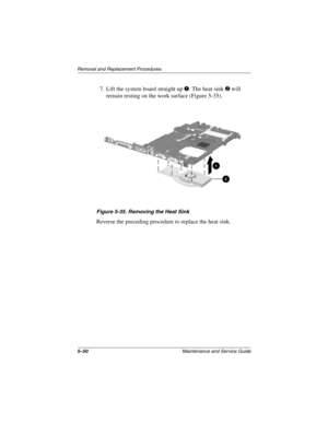
7. Lift the system board straight up 1. The heat sink 2 will
remain resting on the work surface (Figure 5-35).
Figure 5-35. Removing the Heat Sink
Reverse the preceding procedure to replace the heat sink.
279362-001.book  Page 50  Monday, July 8, 2002  11:49 AM
Page 140
Removal and Replacement Procedures
Maintenance and Service Guide5–51
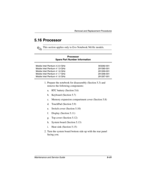
5.16 Processor
✎This section applies only to Evo Notebook N610c models.
1. Prepare the notebook for disassembly (Section 5.3) and
remove the following components:
a. RTC battery (Section 5.6)
b. Keyboard (Section 5.7)
c. Memory expansion compartment cover (Section 5.8)
d. TouchPad (Section 5.9)
e. Switch cover (Section 5.10)
f. Display (Section 5.11)
g. Top cover (Section 5.12)
h. System board (Section 5.13)
i. Heat sink (Section...
