Yamaha As201 Manual
Here you can view all the pages of manual Yamaha As201 Manual. The Yamaha manuals for Receiver are available online for free. You can easily download all the documents as PDF.
Page 2
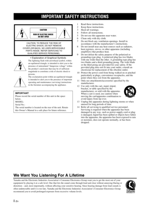
IMPORTANT SAFETY INSTRUCTIONS
i En Explanation of Graphical Symbols
The lightning flash with arrowhead symbol, within
an equilateral triangle, is intended to alert you to the
presence of uninsulated “dangerous voltage” within
the product’s enclosure that may be of sufficient
magnitude to constitute a risk of electric shock to
persons.
The exclamation point within an equilateral triangle
is intended to alert you to the presence of important
operating and maintenance (servicing) instructions
in the...
Page 3
IMPORTANT SAFETY INSTRUCTIONS
ii En
FCC INFORMATION (for US customers)
1IMPORTANT NOTICE: DO NOT MODIFY THIS
UNIT!
This product, when installed as indicated in the
instructions contained in this manual, meets FCC
requirements. Modifications not expressly approved by
Yamaha may void your authority, granted by the FCC,
to use the product.
2 IMPORTANT:
When connecting this product to
accessories and/or another product use only high quality
shielded cables. Cable/s supplied with this product MUST...
Page 4
CAUTION: READ THIS BEFORE OPERATING YOUR UNIT.
iii En
1 To assure the finest performance, please read this manual carefully. Keep it in a safe place for future reference.
2 Install this sound system in a well ventilated, cool, dry,  clean place - away from direct sunlight, heat sources,
vibration, dust, moisture, and/or cold. For proper
ventilation, allow the following minimum clearances
around this unit.
Top: 30 cm (11-3/4 in)
Rear: 20 cm (7-7/8 in)
Sides: 20 cm (7-7/8 in)
3 Locate this unit away...
Page 5
1 En
PREPARATION
INTRODUCTION
BASIC
OPERATION
ADDITIONAL
INFORMATION
ADVANCED
OPERATION
English
USEFUL FEATURES ............................................ 1
SUPPLIED ACCESSORIES ................................. 1
CONTROLS AND FUNCTIONS ......................... 2
Front panel ................................................................. 2
Front panel display .................................................... 4
Rear panel .................................................................. 5...
Page 6
2 En
INTRODUCTION
1A (power)
Turns this unit on, or sets it to standby mode.
This unit consumes a small amount of power even when in
standby mode.
2 FM MODE
Changes the FM radio wave reception mode (stereo or
monaural) when TUNER is selected as the input
source (see page 14).
3 Remote control sensor
Receives infrared signals from the remote control.
4 STANDBY/ON indicator 5
MEMORY
Stores the current FM/AM station as a preset when
TUNER is selected as the input source (see page 15).
6 FM/AM
Sets the...
Page 7
CONTROLS AND FUNCTIONS
3 En
INTRODUCTION
English
0PHONES jack
Outputs audio to your headphones for private
listening.
Press SPEAKERS A/B so that the SP A/B indicators (see
page 4) turn off before you connect your headphones to the
PHONES jack.
ASPEAKERS A/B
Turns on or off the speaker set connected to the
SPEAKERS A and/or SPEAKERS B terminals on the
rear panel each time the corresponding button is
pressed (see page
12). B
BASS –/+
Increases or decreases the low frequency response.
Control range:...
Page 8
CONTROLS AND FUNCTIONS
4 En
1PRESET indicator
2 MEMORY indicator
3 SP (SPEAKERS) A/B indicators
Light up according to the set of speakers selected.
Both indicators light up when both sets of speakers are
selected. 4
TUNED indicator
Lights up when this unit is tuned in to an FM or AM
station with a  strong signal.
5 SLEEP indicator
Lights up when the sleep timer is turned on (see
page 13).
6 ST indicator
Lights up when this unit is in stereo mode and tuning
in an  FM station with a stereo broadcast.
7...
Page 9
CONTROLS AND FUNCTIONS
5 En
INTRODUCTION
English
1ANTENNA terminals
Used to connect FM and AM antennas (see page 11).
2 Power cable
For connecting this unit to an AC wall outlet (see
page 11).
3 CD jacks
Used to connect a CD player (see page 9).
4 LINE 1-2 jacks
Used to connect audio components (see page 9). 5
LINE 3 jacks
PB (Playback) jacks
Used to connect to audio output jacks of an audio
component.
REC (Recording) jacks
Used to connect to audio input jacks of an audio
component.
6 SPEAKERS...
Page 10
CONTROLS AND FUNCTIONS
6 En
■Common controls
The following parts and controls can be used no matter
which input source is selected.
1Infrared signal transmitter
Sends infrared signals.
2
A (power)
Turns this unit on, or sets it to standby mode.
3 SLEEP
Sets the sleep timer (see page 13). 4
Input selector buttons
Select the input source you want to listen to.
y
• The input source names correspond to the names of the
connection jacks on the rear panel.
• To select TUNER as the input source using the...


