Acer Aspire 5534 Service Guide
Here you can view all the pages of manual Acer Aspire 5534 Service Guide. The Acer manuals for Notebook are available online for free. You can easily download all the documents as PDF.
Page 71
Chapter 361
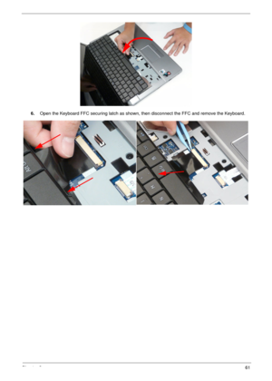
6.Open the Keyboard FFC securing latch as shown, then disconnect the FFC and remove the Keyboard.
Page 72
62Chapter 3
Removing the Upper Cover
1.Remove all external modules. See “External Modules Disassembly Flowchart” on page 45.
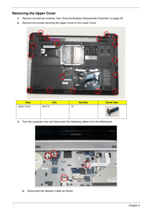
2.Remove the screws securing the Upper Cover to the Lower Cover.
3.Turn the computer over and disconnect the following cables from the Mainboard:
a.Disconnect the Speaker Cable as shown.
StepSizeQuantityScrew Type
Upper Cover M2.5*8 18
Page 73
Chapter 363
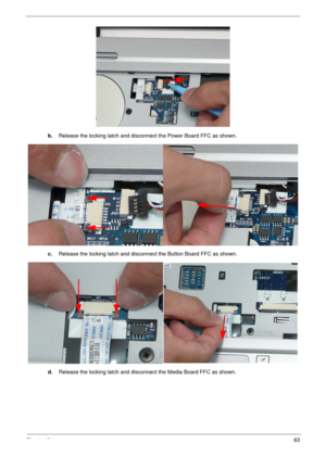
b.Release the locking latch and disconnect the Power Board FFC as shown.
c.Release the locking latch and disconnect the Button Board FFC as shown.
d.Release the locking latch and disconnect the Media Board FFC as shown.
Page 74
64Chapter 3
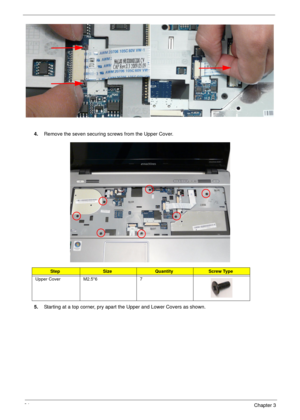
4.Remove the seven securing screws from the Upper Cover.
5.Starting at a top corner, pry apart the Upper and Lower Covers as shown.
StepSizeQuantityScrew Type
Upper Cover M2.5*6 7
Page 75
Chapter 365
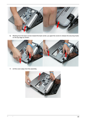
6.Working from the back corners toward the back center, pry apart the covers to release the securing hooks
on the top edge as shown.
7.Lift the cover away from the assembly.
Page 76
66Chapter 3
Removing the Button Board
IMPORTANT: The Touchpad Board cannot be removed individually. To replace the Button Board, replace the entire
Upper Cover.
1.See “Removing the Upper Cover” on page 62.
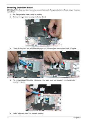
2.Remove the mylar sheet covering the Button Board.
3.Lift the securing latch and disconnect the single FFC connecting the Button Board to the Touchpad.
4.Pull the Mainboard FFC through the opening in the upper cover and separate it from the adhesive
securing it in place.
5.Detach the button board...
Page 77
Chapter 367
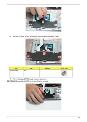
6.Remove the three screws securing the button board to the Upper Cover.
7.Pull the Mainboard FFC through the cover as shown.
IMPORTANT: Ensure that the FFC is not torn off during removal.
StepSizeQuantityScrew Type
Button Board M2*3 3
Page 78
68Chapter 3
Removing the Touchpad Bracket
1.See “Removing the Button Board” on page 66.
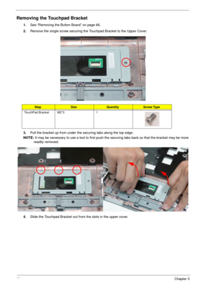
2.Remove the single screw securing the Touchpad Bracket to the Upper Cover.
3.Pull the bracket up from under the securing tabs along the top edge.
NOTE: It may be necessary to use a tool to first push the securing tabs back so that the bracket may be more
readily removed.
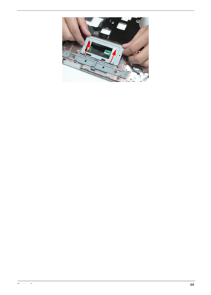
4.Slide the Touchpad Bracket out from the slots in the upper cover.
StepSizeQuantityScrew Type
TouchPad Bracket M2*3 1
Page 80
70Chapter 3
Removing the Power Board
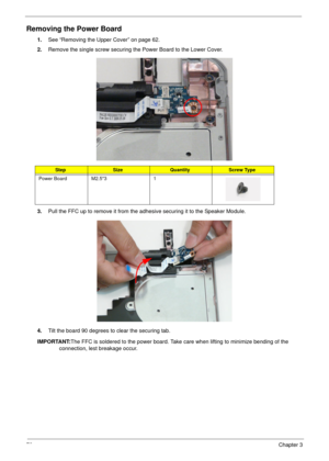
1.See “Removing the Upper Cover” on page 62.
2.Remove the single screw securing the Power Board to the Lower Cover.
3.Pull the FFC up to remove it from the adhesive securing it to the Speaker Module.
4.Tilt the board 90 degrees to clear the securing tab.
IMPORTANT:The FFC is soldered to the power board. Take care when lifting to minimize bending of the
connection, lest breakage occur.
StepSizeQuantityScrew Type
Power Board M2.5*3 1
